Tara Retrofit
Background
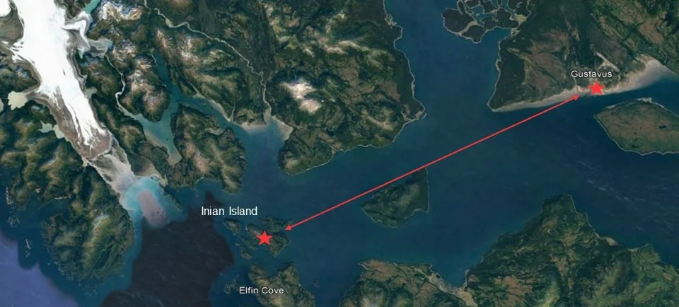
Tidelines Institute, a Southeast AK-based leader in environmental education and research, requiresd a more environmentally friendly propulsion system for their vessel, Tara, to transport students between their two campuses.
My role
Project manager and consultant in a 5-peson team of student engineers.
Objective
Design a more environmentally-friendly propulsion system for Tara that allows Tidelines Institute to reduce their dependence on fossil fuels and facilitate ease of transportation between their two campuses.

Scope
September 2021- March 2022
Culminating Project in Engineering Design
Significance
The basis of our solution stems from the mission of Tidelines. The refit of Tara will not only serve as an environmental effort to make transportation more sustainable for Tidelines, but also serve as a financial effort to reduce costs. Fishing vessels that convert to hybrid-electric motors can experience a 35% reduction in fuel costs.
At a grander scale, our solution also aims to inspire innovation among maritime states, in particular in Alaska. As Alaska is a major maritime state, Tara will be able to serve as an example for future electrification of fishing and other vessels.

Scoping the Problem
To begin defining our user-side specifications, we developed a description of operation document that details:
Information about the vessel’s areas and seasons of operation
Expected weather conditions
Significant east-west tidal currents
Refueling and charging infrastructure at Tara’s home port and ports of call
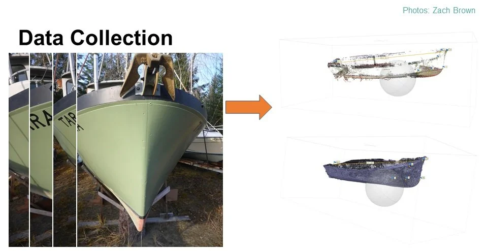
Data Collection
Because the team was based in Hanover, NH, and Tara was in Gustavus, AK, we did not have an adequate idea of the dimensions of the boat. To get a better sense of Tara’s exterior, we performed a photogrammetric analysis to generate point cloud representing of Tara’s hull. This allowed us to generate a mesh from a series of photographs captured by the CEO who was on-site. We used the mesh to validate the proportions of our exterior CAD model later in the design process.
Then, to better understand Tara’s interior layout, framing, and bulkheads, we exchanged a series of sketches with on-site members of the Tidelines staff. They noted measurements and corrections. This allowed us to determine the placement of all the components of the retrofit.


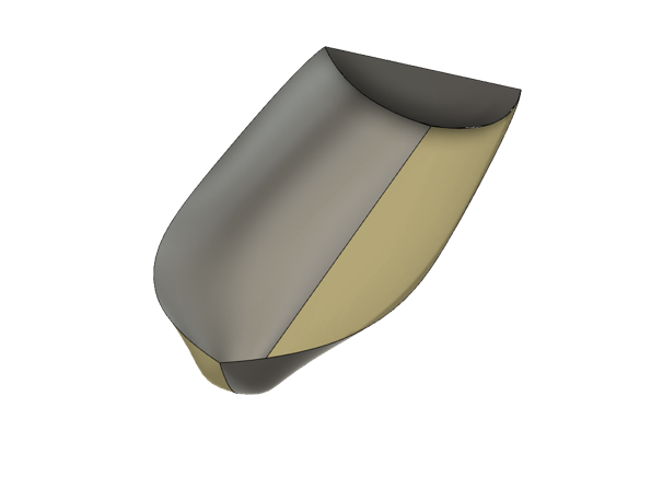
In addition to the photogrammetry, we also created a CAD design of the entire hull. For our CFD simulations, we identifed three main goals:
Determine the role of drag when determining the power use of different speeds of the boat
Conduct stability analysis to ensure optimal use given varying weights of the components
Find the relationship between weight and optimal operating use
We also needed to get some idea of Tara’s performance in the water to properly size components. For a boat that hasn’t been in the water and has next to no operational data logs, we found it to be necessary to use the data of similar vessels. We were provided with datasets for two boats with similar sizes and functionality.


Trip Analysis
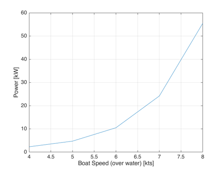
To better define the reasonable range of Tara’s operating conditions, we examined the speed of Tara at the speed that we would expect at location of operation. This allowed us to calculate expected trip durations and further reduce our design space. This yielded another important spec; we must maintain or improve cruising speed.
Once we had our drag curve, these calculations were easily extrapolated to determine the average power calculate total energy of a trip, which yielded specifications for battery size and fuel capacity.
Operational Model
Using the operational data from the two boats, we created a fully parameterized operational model in MATLAB, that we used to determine the sizing of the components. The model also allowed us to set expectations for performance, by calculating boat speed, power, and energy requirements for the trip, fuel consumption, and costs.

Summary of outputs
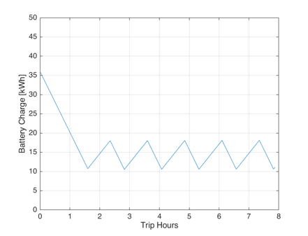
The MATLAB model revealed a number of important insights about the performance of Tara:
Power curve: when approaching above hull speed of 7.5 kts, the power requirements increase significantly
Motor is sized to reach hull speed at wide open throttle (WOT)
Time series of the battery loads showed the effects of charging thresholds, rates, and discharging rates
Solution Design

With the specifications in mind, we have decided to perform a retrofit on Tara that constitutes of:
External charger on shore
Onboard generator, battery bank, electric motor
Motor:
A crucial aspect of our solution space is our choice of motor. Some of the key metrics that lead our choice of motor are power, speed (of the propeller), efficiency, maintenance cost, and weight.
In terms of type of motor, there are two types: inboards and outboards.
For inboards, there are really only two that are appropriate for marine application: induction AC and permanent magnet AC.

Some reasons to go with a permanent magnet motor are:
Maintenance costs: induction motors are easier to repair and maintain, which is very important considering Tara’s remote operation location.
Price: for a given power, an induction motor is going to be cheaper.
Other reasons to go with a permanent magnet motor are:
Weight: they tend to be much lighter than an equivalently sized induction motor
Higher inherent efficiency
For outboard motors, most outboard motors are permanent magnet motors. Reasons to go with outboards are:
De-risking: compatibility with the current transmission of the vessel is not necessary. This would render the installation process a lot easier.
Safety: if we choose to go with an outboard motor, two outboard motors will be installed side by side, and the probability that both of them will fail (and that Tara will be stranded) is highly miniscule
Batteries:
Thinking about rechargeable batteries, we had to examine our choices against some metrics:
Capacity: we need a big enough battery to store substantial power from the shore.
Performance at cold temperatures: the capability of the batteries to charge and discharge in cold temperatures is vital for a boat that is to operate in Alaskan waters.
System compatibility
Lifetime: it has to live long enough to justify upfront cost
Weight of the vessel
Bearing these factors in mind, we found only two options for rechargeable batteries: Lithium ion or AGM (lead acid). Between the two, lithium ion batteries are best suited for our application. Although both perform similarly when it comes to capacity, temperature performance, and compatibility, lithium ion batteries have greater depth of discharge; they have more available energy.

Generator set:
We were quickly able to pare down the solution space because of key factors that guided our research:
Fuel availability: available fuel docks only have diesel, so it is not worth considering alternative fuels.
Output power: to maintain charge at WOT, we need to maintain output power of 25-30kW
Physical dimensions and weight

System Diagram:
After researching our solution, we created a high-level circuit diagram for our proposed system.
This first box encircles the genset subsystem, consisting of the genset, its integrated controller, and a double pole switch that switches between that and shore power.
This second box encircles the battery subsystem, consisting of three sets of two fused-up lithionics batteries in parallel, each with its own associated charger and BMS system. The BMS flips the generator on and off through a digital output signal.
This third box encircles the motor subsystem, consisting of the motor with its integrated controller, that interfaces with the helm through a multi conductor cable; there is also a manual emergency disconnect switch, so that the motor may be isolated from the rest of the system.

CAD of interior:
We then placed our components in our CAD design of the vessel. If we take a look inside the interior, we can see the setup. In the back is the fuel tank, followed by the batteries, motor, and genset. The decisions of the placement of each component was based on space available as well as the existing setup currently on Tara.

Verification
Buoyancy analysis:
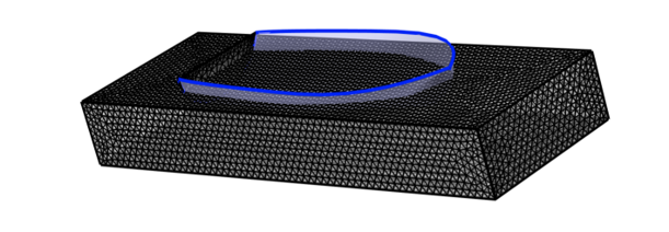
To verify that the boat will be stable and float, we conducted a buoyancy analysis. For this analysis, we took into account loading dimensions such as the weight and volume of the hull, specific gravity of salt water, and other loading factors. This results in a total load of approx. 5004 lbs.
To calculate buoyancy, we first solved for the waterline by calculating (analytically) the water displaced. We took the total weight of the boat and divided it by the specific gravity of saltwater and found the water line, which shows where the volume at which the boat will be the underwater.
After calculating the water line we did this computationally for a more robust analysis. For this analysis, we found the location of the water line to be the same as the one we calculated. The volume of the hull shown in the image is the volume of the hull that would be underwater. The circle in the middle that you see represents the center of buoyancy of our boat. Overall, we can say with confidence that the boat will indeed be stable and afloat.

After proving the buoyancy of the boat, we then conducted an analysis to check that the loading on the boat would not be enough to cause stability issues. For that we conducted a static study and added the forces acting on the boat. The purple arrows represent the loading on the boat. The green arrows represent fix points on the boat. And the red arrow is the force of gravity acting on the boat. In running the simulation, we found the stress to be evenly distributed throughout the hull, which shows that the boat will be stable even with the additional loading.
Aside from stress, we also calculated displacement and strain and found the results to be consistent to that of our stress results.

The project was proved feasible and set a new standard for marine hybrid propulsion. The solution is currently being implemented by Tidelines Institute in preparation for their summer classes.
Feel free to read our report included below.