Micromouse
My role
Designing the micromouse chassis; Manufacturing and assembling the robot; Sensor integration, Low-level controls (turn and braking), and Software design and implementation (maze solving algorithm)
Tools
SolidWorks, laser cutting, rapid prototyping, 3D printing, Arduino, C
Objective
To design, fabricate, and program a robot to find its way from the start area of a maze to the finish area at the center of the maze autonomously, without human intervention, in the shortest time.
Scope
May 2023
Design, fabrication, and implementation (Software and Hardware)
Final Result
This is a video of our micromouse finding its wasy to the center of the maze. So, how did we get there? Keep reading!


Process
Analyzing the Problem > Sketching > Sensor & Motor Selection > 3D Modeling > Iterative Manufacturing & Assembly > Low-level control > Software Design > Algorithm Implementation > Competition
Sketching
We were given the general objective and a lot of freedom. Therefore, we started by brainstorming chassis designs and component placements .
Design Principle: Keep it simple! The simpler the design, the easier it is to build the robot and give it maximum navigability during the competition.
A surface of 20x12 cm would be sufficient to house all of our parts. We considered either 3D printing our chassis out of PLA or laser cutting it in acrylic, and decided on the latter due to the simplicity of the designs. The sketches below outline two ideas of how we are considered assembling the micromouse on top of the chassis. We considered stacking components on top of each other for more efficient use of space. The pictures below showcase some of the sketches I created:


Component Selection
Motors
The only constraint that we framed our research was that our components had to be purchased from Polulu. Based on our needs, it was best to use two 125:1 20Dx44L mm, 12V motors. Considering worst-case scenarios where the micromouse would weigh 0.9 kg, and rolling resistance coefficient would be about 0.1 (which, in reality, is closer to the resistance between tires on gravel or sand), and where the wheels are approximately 5 cm in diameter, the torque that would need to be overcome is 0.1*0.9*2.5cm = 2.205 kg*cm, or 1.1025 kg*cm per motor.
We aimed to keep the motors operating in the region of maximum efficiency. Because using the motor at 9.6 V will lower stall torque by 20%, we needed to go pick a motor with a higher stall torque. The motor we have chosen delivers a stall torque of 7.8 kg*cm at 12 V, which would be 6.24 kg*cm at 9.6 V. Polulu lists the torque at maximum efficiency at 1.3 kg*cm. Reduced by 20%, this results in a max efficiency torque of 1.04 kg*cm, slightly lower than the torque to be overcome by each motor.
We expect motors to be among the heavier components of the micromouse, but the motors we have picked contribute a combined weight of 92 grams to the total weight – making them significantly lighter than other options. This type of motor will also operate at decent speeds – at maximum efficiency, the motor rotates at 94 rpm. With a lower mass and resistance coefficient, the motors may operate closer to 100 rpm or higher.
Sensors
Sensors are the means through which the micromouse will detect walls and traverse the maze with proper alignment in the center of a pathway. Thus, sensors give the robot the means to understand its environment. In the market, there are few categories of sensors that can do this:
Sonar sensors
IR distance measuring sensors
Time of Flight (ToF) sensors
We decided to compare these sensors under a few parameters that are more relevant to our application.
Reaction time — speed
Accuracy
Range
Physical size
Price
Compatibility with Arduino
The ideal case was to find a small, high speed, low cost sensor that can take the reading in the expected range with higher accuracy. The time taken by the sensors to give the distance readings and their accuracy also affects the motion of the micromouse. If your sensors are too slow, then sometimes you might have to reduce the speed of the mouse. If your sensor readings are not accurate, then there’s a possibility of making a wrong move by the mouse.
From the above criteria, we could clearly identify IR and ToF sensors as the most suitable for our application. However, although more costly, IR sensors are faster than ToF sensors, as well as easier to implement. Since both of the sensors are suitable for our application, we decided to go with IR sensors.
Based on our needs, we chose three GP2Y0A60SZLF Analog Distance Sensors, as listed on Pololu; two will point sideways, just ahead of the wheels, to help steer straight down hallways and keep the micromouse in the center of a pathway; one will point forward to watch for walls ahead of the robot.
SolidWo3D Modeling
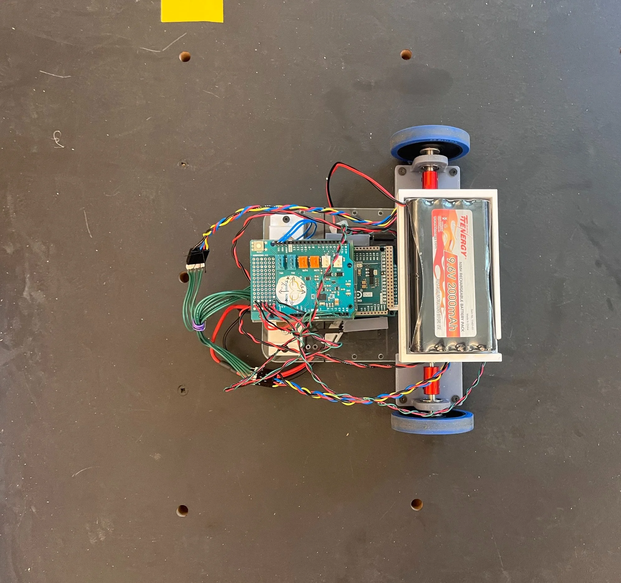
Below are different views of the assembled robot, whish I modeled in SolidWorks. The model includes the chassis body (¼’’ laser cut acrylic), the two motors, the two wheels, and the senosors, with all the necessary attachments, which were 3D printed.


Low-level Control
Motor Characterization
Velocity data was collected for a range of PWM commands and steady-state velocity and time constants were then calculated from the data. This helped us determine the maximum speed (8 rad/sec = ~0.25 m/s) and the operational Tau (52.5 ms).


Voltage and PWM Fitting
We also found the relationship between voltage and PWM commands.


IR Sensor Calibration
I also wrote Arduino code to retrieve analog values from the sensor:
In the code, a mean of 500 readings is calculated in order to null down the outliers
I then used the regression using the Excel function and wrote another Arduino program to retrieve the distance values properly

Data Collection
After characterizing our components, we started working on the functions that will interact with the hardware directly.
A data collection function is used at a consistent sampling interval to measure necessary data and allow the information to be grabbed by any function when called
All information is stored in a uniform buffer size (201 values currently) which can then be printed and analyzed outside of runs
A global array index variable was used to easily access recent or past data values anywhere in the code
Important data that is stored:
Time since the program has begun
IR sensor distances (for the front, left, and right sensors)
Motor positions and velocities
Applied control effort (in voltages and in PWM commands)
Micromouse heading (its angle in degrees) and orientation (North, South, East, or West)
Orientation is determined during initialization in which a “true” north is defined
Speed Control
We used discrete approximation to create our desired compensator. The PID compensator was used to increase system type and increase the transient performance of the system.
Design Specs:
Settling Time: <0.5 sec
Damping Ratio: >0.6
Steady State Error: 0%
Control Effort: <9.6 volts
Implementing the difference equation shown below, we were able to achieve nearly all of our design specifications. A settling time of roughly 0.8 sec provides a snappy response for the robot to operate in the maze.


Turn Control
A proportional controller is used to control the turning of our micromouse.
The desired turning angle (0˚, 90˚, 180˚, or 270˚) and the initial micromouse angle are passed through the function. Based on the initial orientation of the micromouse, the robot will turn.
The control was done by plotting a function using a maximum motor speed and minimum motor speed. You could find the line function that goes through the points (0,2) and (target angle, 8). This will ensure that the motors spin slower as the target angle is reached.
2 and 8 are the minimum and maximum desired motor speeds (rad/sec).
With this form off turn control we are able to consistently get within 5˚ of our turning angle each time.


Braking Control
Proportional gain is used to moderate the micromouse’s distance from its front wall. As the micromouse approaches the reference distance, the motor speed is reduced. A reference distance of 9cm was used in implementation.

Wall Following
Wall following is broken up into 2 main control loops
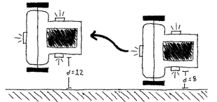
The first moderates the distance of the micromouse from either side walls. If the mouse is too close to a wall (within 12cm) the same-side motor increases its speed
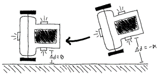
The other loop moderates the change in the distance between the micromouse and the side walls. If the mouse is approaching the side wall from an angle (not parallel with it) the system will correct itself to ensure there is no change in wall distance.
A proportional gain was used for each of these quantities to push/pull the micromouse from/to the walls as needed.
Software Design
For our high level logic, we decided to pursue a heuristic algorithm to always turn right if possible. The stopping condition is when the mouse made 3 consecutive right turns.
We also explored the flood fill algorithm, using a 2D maze array and a queue implemented as a circular array, as well as cell structures for information on each cell. This algorithm would allows the mouse to find the optimal path if it could run through the maze a second time.
State Machine
The process begins in the driving state since we know the start of the maze will have the mouse surrounded by walls on 3 sides
If a front wall is detected within 25 cm of the mouse the process is shifted into the braking state
Else, the surrounding walls are checked every 2.35sec (from the cruising speed of our mouse, this is how long it takes to move from cell to cell
After the surrounding walls are measured an saved, a decision is made on the direction to turn
Turn priority: Left > Right > Straight > Turn Around

Deciding Target Turning Angles
Upon initialization of the mouse the Arduino 9-Axis Motion Shield sets the orientation of the unit circle which is held absolute for the rest of the run (which we define a “True North”)
Therefore, the target angles we pass into the turner() function are dependent on the current orientation of the mouse (please note the diagram below)

Feel free to check out the code here.
Lessons Learned
As we’ve learned during testing, a smaller, lighter mouse is easier to control and performs better in the maze, as it can tolerate more error with motion control and can complete the maze faster. A potential design improvement would be choosing smaller motors and trying to either get rid of couplers entirely or buy/design smaller ones.
Time management could have been better and a few of our smaller deadlines were missed. This added up and meant that towards the end of the project there was a lot left to do. This resulted in a few gaps such as the flood-fill algorithm not getting finished to the standard that we had hoped for at the beginning of the project.