Text-to-Morse Code Translator
Objective
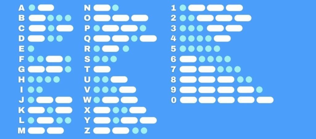
Create a serial to Morse code translator using VHDL code, WaveForms software, AD2 board, and a Basys-3 FPGA integrated circuit board. The Morse code signal is generated in two ways. First, the LEDs on the Basys3 board will light up whenever the output should be “on.” Second, a sound output is generated that creates a beeping sound whenever the output is “on.”
Theory of Operation
In order to decide what letters the Morse code generator will make, we sent characters to the Basys3 board using the Serial Communications Interface (also commonly known as UART or RS-232). We generated the SCI signal using the Waveforms software and the AD2 board. This was sent to one of our digital I/O pins on the Basys3. The data will take the form of an 8-bit ASCII character. We had to design the circuitry to receive this data and convert it to some sort of appropriate format to allow for the output of the Morse code signal.
Implementation
The functionality of the system relies on the correct implementation of 8 small functional blocks: SCI Receiver, SCI Transmitter, Check Character, Buffer, Morse Translator, Morse interpreter, Square Wave Oscillator, and Final MUX. The SCI blocks receive the binary data coming from the AD2 block and concatenate them in ASCII formatting. The characters are then sent back to the AD2 so the user can see on the screen their input. The SCIs work at a baud rate of 9,600 bits/sec. The Check Character block verifies if the enter key has been pressed to trigger the translation of the bits in the system. The Buffer stores the characters inputted by the user, while the Translator transforms each bit into its Morse code equivalent – a representation of dots (01) and dashes (11). The Interpreter uses such formatting as a time indicator for the sound and light signals. The Square Wave Oscillator and Final MUX blocks take care of the audio aspect of the system. They generate square waveforms with ideal frequencies to form pitches recognizable to human ears (500Hz). The result of each component block is satisfying and in alignment with the specifications for the whole system. Our design went through synthesis, implementation and bitstream generation successfully.
Feel free to go through our report below which includes our code!